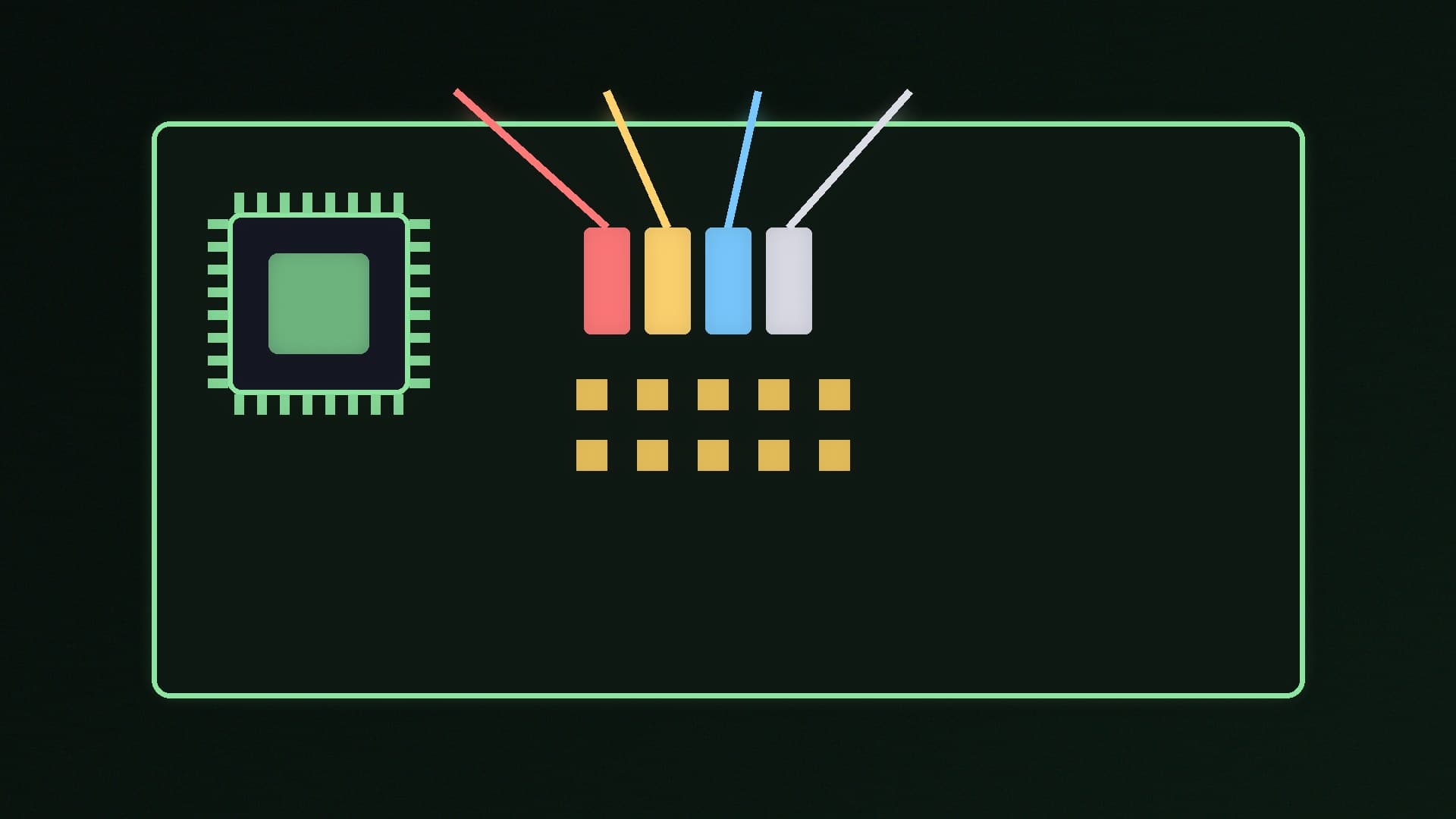
Every PC case has a bundle of small cables that run from the front panel to the motherboard: the power button, reset button, power and drive activity lights, USB ports and headphone jack. They are easy to overlook and fiddly to fit, and a power switch cable on the wrong pins is one of the most common reasons a freshly built PC does nothing when you press the button.
This guide is based on ASUS's official Motherboard Installation Guide (revised January 2026), which covers its current boards; other makers use very similar layouts. Forge PC has not tested every case and motherboard combination, so always check your own motherboard manual for the exact pin layout.
Before you start
Switch off and unplug the PC at the wall before you touch any cables.
Find the pin diagram. Your motherboard manual has a diagram of the front panel header and its pins. ASUS says the front panel connector varies between motherboard models, so use the diagram for your exact board.
Have a torch handy. The pins are small and easy to misread in a dark case.
ASUS lists these front panel connector pins:
Label | What it does | Orientation |
|---|
PWRSW / PWRBTN | Power switch | None, either way round |
RESET | Reset switch | None, either way round |
PLED | Power LED | Matters |
HDD_LED / HDLED | Drive activity LED | Treat as polarised, like PLED |
SPEAKER | System speaker | None, either way round |
CHASSIS | Chassis intrusion (on some boards) | See manual |
Your case's cables should be labelled with matching names, such as POWER SW, RESET SW, POWER LED and H.D.D. LED. ASUS says the front panel cables of your case "may differ with models or designs", so connect them according to the labels.
Step 1: Connect the power and reset switches
Push the power switch cable onto the PWRSW pins and the reset switch cable onto the RESET pins shown in your manual. ASUS says the power switch, reset and speaker cables have no specific orientation, so they work either way round. Push each one straight down until it is fully seated.
If your case has no reset button, simply leave those pins empty.
Step 2: Connect the LEDs the right way round
The LED cables do have a polarity. For the power LED, ASUS's advice is to match PIN1 on the cable to PIN1 on the motherboard, and it notes that the white wire usually stands for ground while the colour-coded wire is the signal. Check your manual's diagram to see which pin is which.
If an LED does not light up but you are sure it is on the right pins, ASUS says you might have mistaken the ground pins for the signal pins. Turn the connector round and try again.
Step 3: Use a Q-Connector if your board has one
Many ASUS boards come with a Q-Connector, a small adapter block printed with the pin names. You plug each case cable into the block on your desk, where you can see what you are doing, and then push the whole block onto the motherboard header in one go. ASUS's guide shows it for its 20-3 pin, 20-5 pin and 10-1 pin front panel layouts. Check your motherboard box to see whether one is included.
Step 4: Connect the front USB and audio cables
The bigger front panel cables are easier, but they still need care. ASUS's guide shows four of them:
USB-C front port: ASUS covers the USB 20Gbps, 10Gbps and 5Gbps Type-C headers and warns that the connector only fits in one orientation. Push it in until it clicks into place, and never force it.
USB 5Gbps header: the larger plug for the case's front USB-A ports.
USB 2.0 header: a smaller plug, used for older front USB ports and some internal accessories.
Front panel audio (F_AUDIO): the headphone and mic jacks on the front of the case.
Check the plug against the header and the diagram in your manual before pushing, so that no pins are left out or bent.
Step 5: Test before you close the case
With everything connected, plug the PC in and press the power button. If nothing happens, check the power switch cable first: it is the most likely to be on the wrong pins or not pushed fully home. If the PC starts but an LED stays dark, turn that LED connector round. Our guide on what to do when a PC won't turn on or boot covers other causes if the front panel is not the problem.
If you are part-way through a new build, our complete guide to building a gaming PC shows where this step fits.
Our verdict
Connecting front panel cables is easy once you know the rules. Find the front panel header diagram in your manual, connect the power and reset switches either way round, and fit the LEDs the right way round, with the colour-coded signal wire and the white ground wire on the pins your manual shows. Use a Q-Connector if your board includes one, and line up the USB and audio plugs carefully before pushing them on gently. If a new PC will not start, check the power switch cable first. This guide follows ASUS's official installation guide; always check your own motherboard manual for the exact layout.